Vibrator Telegraph
| Vibrator Telegraph | |
|---|---|
 |
Description
Vibrator Telegraph[1]
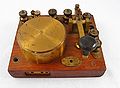
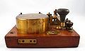
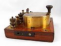
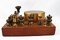
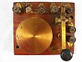
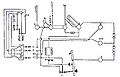
269. This instrument consists of a electro-magnet, a contact screw Morse key, a bobbin lightning discharger, hand telephone "C" Mk. II or III, a head receiver, and the necessary terminals for connecting up, mounted on a wooden base.
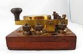
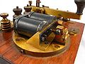
A battery of 6 cells inert "O" is used with the set. The armature of the electro-magnet is made of a strip of steel. The connections are so arranged that, on the key being depressed, the battery current is sent through the electro-magnet and the contact made by the screw on the armature. The armature is at once attracted, but as soon as it moves, it breaks the circuit at the screw-contact. As soon as the circuit is broken the electro-magnet ceases to attract the armature, which springs back again and makes contact with the screw. This process is repeated so long as the key is kept depressed, and the vibration of the armature thus produces a buzzing sound.
One of the line wires is connected to the "L" terminal through a bobbin lightning protector, through the receiver (if using a hand telephone, through both receivers in parallel), through magnet coils to Z and E terminals, to earth ; thus each impulse of current through the electro-magnet is also set to line, the two being in divided circuit ; the impulses of the current on the line have the same frequency as those through the electro-magnet ; when received in the receiver they cause the diaphragm to vibrate giving a note similar to that of the armature.
The electro-magnet is wound in parallel, each bobbin having a resistance of 20 ohms.
270. The action of the electro-magnet, on account of it's self induction, increases the strength of signal on the line ; for, when the current starts through the coils, there is produced in it an opposing E.M.F. which increases the strength of the current on the line, and when, by the armature leaving the contact, the battery current is broken, there is produced an E.M.F. which reverses the direction of current in the line.
The vibration signals are received in the receiver of the hand telephone, and also in the head receiver, the two being in parallel, and in series with the line ; the reason of this being that the receiver of the sending station should act the part of a galvanometer and indicate whether the current is going to line.
271. The "Telephone, Hand," C, Mk II or III is attached for use when speech is resorted to.
When the microphone is spoken into, the variations in it's resistance affects the current through the coils of the electro-magnet, which act as an induction coil in an ordinary telephone circuit ; the reaction of the magnetic changes also affecting the line signals.
The circuit through the microphone does not, of course, pass through the contact-screw and armature. This circuit is completed by means of a switch in the hand telephone, which is pressed by the hand when speaking.
Attention is called for speaking by means of the vibrator signals, which are sent by working the Morse key as usual. The microphone switch should not be closed when working with the vibrator key.
272. The terminals attached to the instrument are marked with the initial letters of the apparatus to which they should be connected.
The head receiver leads are joined to the terminals marked "R". The only adjustment necessary is that the armature should vibrate freely when the key is depressed, and the contact-screw should be set so as to produce this result. When set it must be firmly clamped.
Six cells are used for the vibrator, two of which are employed for the microphone circuit by connecting the second positive from the negative end of the battery to the terminal "C.M."
The negative of the battery will be common to both the vibrator and microphone circuits.
A condenser of 1/20 Microfarad capacity is inserted between the terminals E and Z, a brass strip being provided to short-circuit the condenser when not required. The condenser is place in circuit by disconnecting the brass strip at E ; this is only done when tapping in on a telegraph line, on which Morse is working, to prevent the telegraph current passing through the vibrator to earth.
273. To test the instrument. - When joined up remove one of the line wires ; depress the key ; sounds should not be heard in the receiver ; or, if heard, they should be at most very faint.
This proves that the instrument is not short circuited. Next, connect terminals L and E by a piece of wire, or the blade of a knife; on depressing the key, loud sounds should be heard in the receiver.
Now disconnect the brass strip from the E terminal and repeat ; sounds should still be heard, if not the condenser is faulty.
274. To test the microphone. - Join terminals L and E by a piece of wire or metal ; close the microphone switch and blow into the microphone ; these sounds should be distinctly heard in the receiver ; if not heard the microphone circuit is faulty.
If the above tests fail, the battery must be tested with a detector, and the whole of the circuits tested for continuity.
275. Discharger, lightning, bobbin, Mark I. - The "dis-charger, lightning, bobbing, Mark I" is used with most of the service field pattern instruments, and consists of a metal reel - (see Fig. 3) - on which are wound a few turns of silk covered wire. This wire forms a portion of the line circuit. The bobbin is connected to earth by being screwed on to an earthed plate, forming part of the set with which it is used. A lightning discharge will break through the insulation to earth, and may even fuse the wire and thus put the line to earth and disconnect the instrument. This discharger is very efficient, and also very compact, but has the disadvantage of usually putting a fault on the line when it acts. It is, however, very easily replaced ; a spare bobbin is always supplied. The wire used in known as "Wire, electric, W3" ; 52 inches are wound on each bobbin.
Photos
Overall view
Front view
Left side view
Right side view
Back view
Top view
Vibrator detail
Bottom view


Related Pages
- No related pages at this time
Related Items
Instruction in Army Telegraphy and Telephony Volume I - Instruments, 1914 - Chapter 15 Figure 8

References
- ↑ extract from "Training Manual - Signalling 1915 (Provisional)"